

Self-cleaning stainless steel tanks | CIP systems and tank
4. Working Principle:
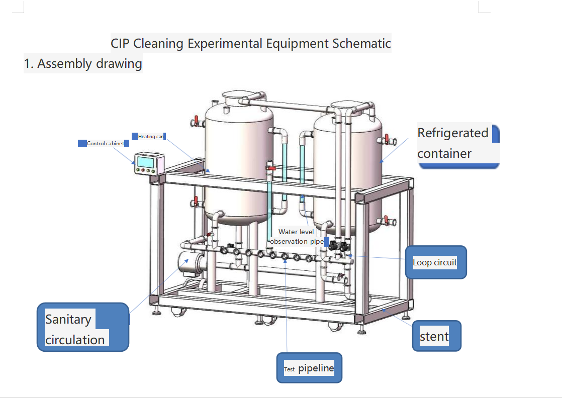
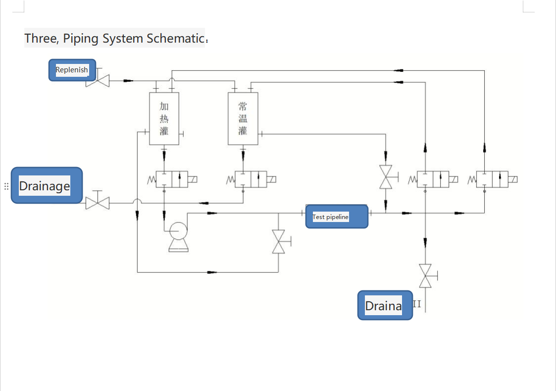
1. Fill the heating tank and the ambient temperature tank with water, set the heating temperature of the tank, and then turn on the switch to start heating;
2. Install the test workpiece on the test pipeline, ensure a reliable seal, and record the point data;
3. Open the manual ball valve of the ambient temperature tank, fill the pipeline to the rated water level, and record the test point data; . When the temperature of the heating tank reaches the set value, press the CIP cleaning button to start the cleaning process. The electromagnetic valve and circulation pump of heating tank will act, and after circulating hot water for several minutes (the time can be set), the electromagnetic valve and circulation pump of the ambient temperature tank will, and after circulating ambient temperature water for several minutes (the time can be set), the process will repeat n times (the number of times can be set) then stop;
5. Open the manual drainage valve, drain the water in the test pipeline, and record the zero point data;
6. Open the manual ball of the ambient temperature tank, fill the pipeline to the rated water level, and record the test point data;
7. Open the manual drainage valve, drain the in the test pipeline, then remove the test workpiece, and install another batch of test workpieces;
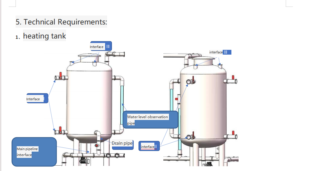
1.1 Heating tank heating temperature: 0-100℃, the heating temperature can be set and displayed;
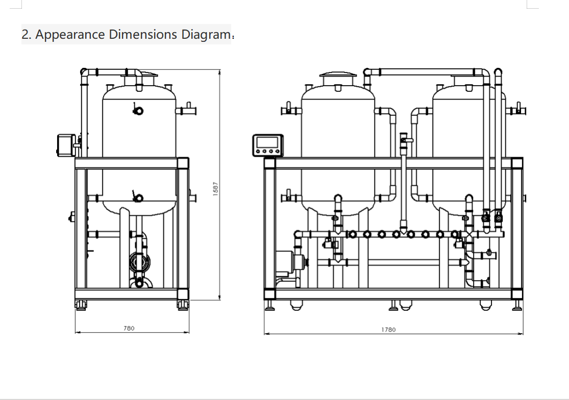
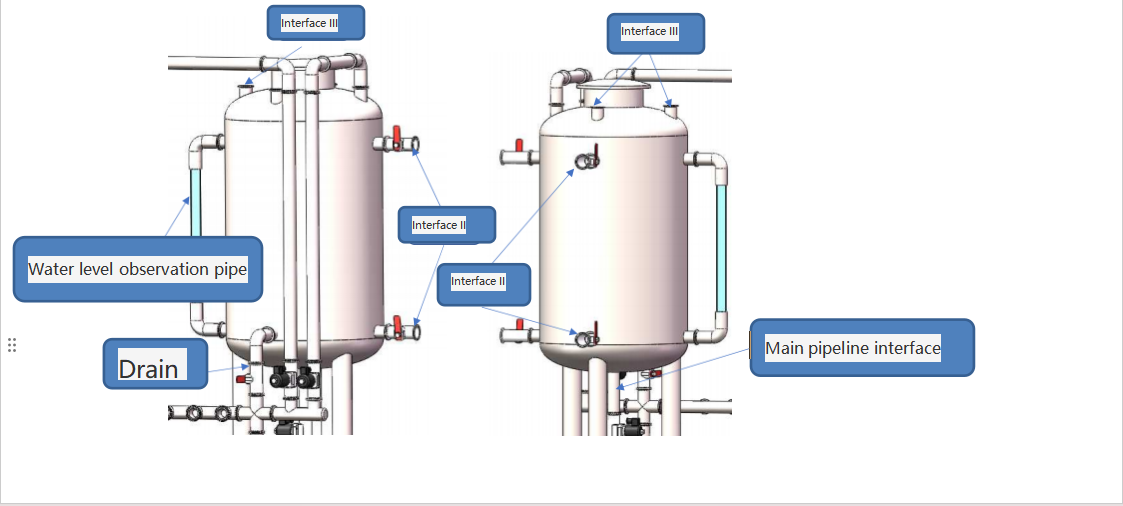
1. Tank size is approximately ∮500mmX1000mm, material is 304, and the volume can be controlled between 6L-140L;
1.3 The tank column needs to be equipped with a water level observation tube (size can be customized), with a center of 600mm;
1.4 The drainage pipe connects to the main pipeline (size can be customized), and a manual ball valve needs to be between the drainage pipe and the main pipeline;
1.5 Interface I size is 1.5-inch clamp, a 1.5-inch clamp manual ball needs to be installed, and the distance between two interfaces is 600mm;
1.6 Interface II size is 2-inch clamp, a 2 clamp manual ball valve needs to be installed, and the distance between two interfaces is 600mm;
1.7 Interface III consists of three 15-inch clamps, and another one connects to the main pipeline (size can be customized);
1.8 The main pipeline interface is DN50, and electromagnetic valve needs to be installed;
1.9 The top of the tank needs to be designed as a removable cover for easy cleaning and maintenance of the tank
2.0 The bottom of the tank adds 2 1.5-inch clamps and 1 2-inch clamp
2、Refrigeration tank
2.1 The size of the ambient temperature tank is approximately ∮500mmX1000mm, made of 04 material, with a volume control of 60L-140L;
2.2 The tank column needs to be equipped with a level observation tube (size can be customized), with a center distance of 600mm;
2.3 The drainage pipe connects to the main pipelinesize can be customized), and a manual ball valve needs to be installed between the drainage pipe and the main pipeline;
2.4 The size of Interface I 1.5-inch clamp, a 1.5-inch clamp manual ball valve needs to be installed, and the distance between two interfaces is 60mm;
2.5 The size of Interface II is 2-inch clamp, a 2-inch clamp manual ball valve needs to be installed, and the distance two interfaces is 600mm;
2.6 Interface III consists of 3 1.5-inch clamps, and another one connects to main pipeline (size can be customized); 2.7 The main pipeline interface is DN50, and an electromagnetic valve needs to be installed;
28 The top of the tank needs to be designed as a lid for easy cleaning and maintenance of the tank;
2.9 The bottom of the tank adds2 1.5-inch clamps and 1 2-inch clamp;
3.0 The refrigeration temperature is 0-20
3.支架
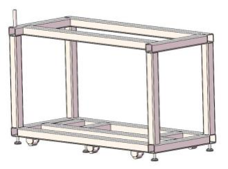
3.1 The rack should be designed to be movable and equipped with ground screws;
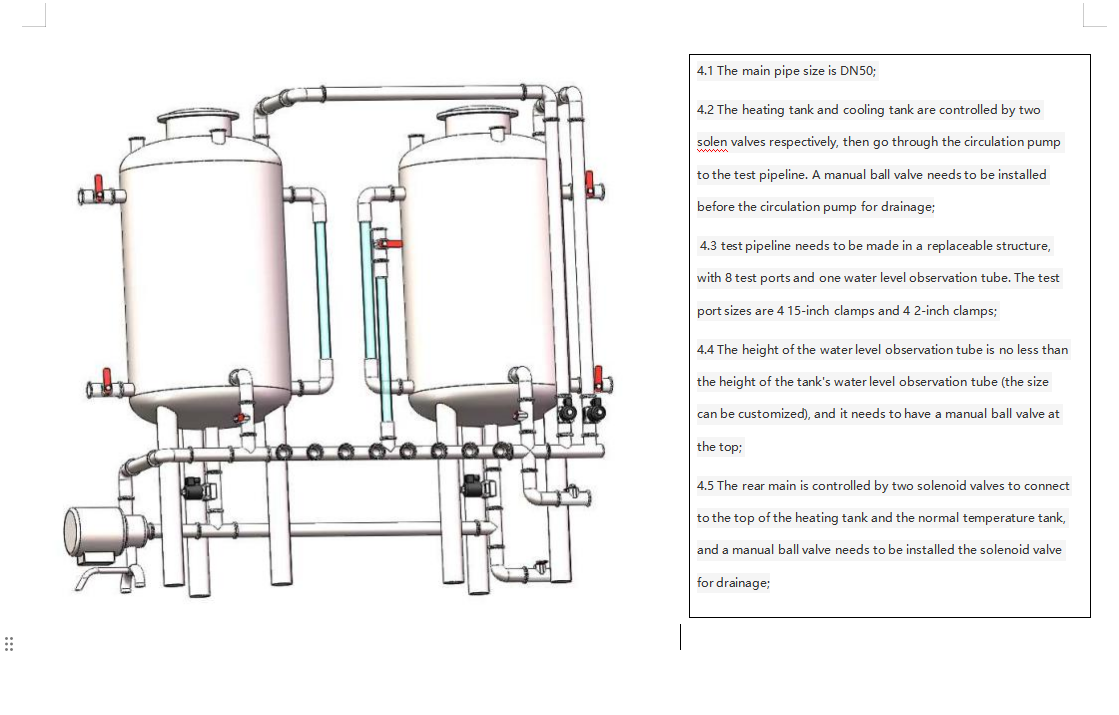
4. Recirculation loop and test pipeline
5. Control cabinet
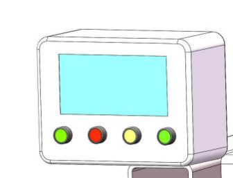
5.1 The control cabinet must display the temperature of the heating tank and the cooling tank, and it should allow for setting the heating and cooling of these tanks; 5.2 It should enable control and setting of the operation time of the circulation pump and solenoid valve, as well as the number cycles; 5.3 It needs power switch buttons, cleaning start buttons, emergency stop buttons, and solenoid valve jogging buttons, etc
Product Description
Condition
The CIP Clean-in-Place (CIP) system is a system that employs the use of automatic equipment for the cleaning of specific pieces of equipment, piping, storage tanks and vessels, ensuring maximum cleanliness and sterility of the production facilities.
Cip clean in place applications
Use of this system enables the effective and efficient internal cleaning of the internal surfaces of pipes, tanks, vessels and various other equipment whereby cleanliness is a major priority. These include:
Food and Processing Industry
The application of cleaning processes for mixing tanks, bottling lines and piping systems without the removal of the production equipment.
Dairy
Cleaning processes of thermos, it’s exciting processes like separating and host tank cleaning so that a conducive production process for milk, cheese products can be ensured.
Chemical
Cleaning of risers and processing tanks in a safe and effective manner, usually in situations where cross-contamination from one batch to another is not permissible.
Biotechnology
Cleaning of fermenters and bio-reactors to ensure that the sterile environment for biological activities.
Advantages of the CIP System
The advantage of the CIP system is that it eliminates any cleaning interruption by supplying a cleaning procedure for all forms and sizes of equipment. All piping including valves and fittings is purged to remove all product residue so that specific functionalities are cleaned.
Material
Most systems applied for CIP cleaning construction comprise materials that are strong enough to endure heavy spraying schedules, strong chemicals, and heat such as over 100°C. Some of the common materials used include:
Stainless Steel (316L)
Stainless steel is very user-friendly as it prevents corrosion and is durable and clean, and is thus an efficient material for over most of the CIP system, particularly where sterilization is key.
High Temperature Seals and Gaskets
These types of seals are made from EPDM, silicone, PTFE, etc. These seals enable it to be watertight and withstand very strong chemicals and heat from the cleaning procedure.
Food Grade Hoses and Tubes
CIP systems therefore include hoses and tubing also which do stand up to chemical cleaning surfactants high pressure and high temperature. These are usually made from food hygienic rubber or stainless steel.
Key Features
Automated Operation
The process occurs without the attendant overseeing it with the CIP System. This means that cycles will clean up then give way for other activities, modernizing the cleaning effort so that it will eliminate manual activity as well as idle time.
Customizable Cleaning Cycles
The cleaning cycles can be adjusted or tailored to suit any specific needs including the temperature, the concentration of the cleaning agent, the nutrients flow rates and the time taken in each stage of cleaning.
Hygienic Design
The system is built in compliance with sanitary systems so that there is no accumulation of bacteria, mold, or any other factors that may pose a threat.
High Efficiency
The use of high pressure jets combined with optimized flow patterns ensures effective cleaning in a shorter period of time with the CIP system, thereby using less water, energy and detergent.
Safety and Compliance
The system has been designed according to the norms of hygiene and safety of the industry including the FDA, EHEDG and 3A Sanitary Standards to be regulatory compliant.
Energy and Water Savings
This in turn sinks the input to the use of less cleaning water by the active CIP system through washing cycles to bring back used washing solutions. Therefore, the active cleaning system application benefits industries with strong commitments toward environmental responsibility.
Functions
Structure of a stand-alone CIP system offering industrial cleaning support functions. The following components provide the necessary functions in order to perform the cleaning processes called CIP in the explore processes of industrial washing.
Pre-Rinse
The program is a pre washing system which operates first in cycle separating thick grease, food particles, and chemicals left to the equipment prior to the use of cleansing agents.
Detergent Wash
Upon completion of the pre wash, the system proceeds to the next cleansing section, where it engages the cleaning circulation of detergents or other cleansing compounds through the equipment to effect stage three of the cleaning process.
Intermediate Rinse
The secondary rinse becomes the final rinse, and any residual detergent anywhere in the production area is removed in order to avoid any contamination.
Sanitization
The system can incorporate a sterilant (such as peracetic acid or sodium hypochlorite) within the cleaning system to ensure that bacteria and all other pathogens are completely eliminated.
Final Rinse
At this stage, the last rinse eliminates all residues of cleaning agents and any sanitizers, and there is sufficient availability of equipment for instant usage.
Usage Instructions
Initial Setup
It is a requirement that the cleaning process be initiated once all the components that constitute the cleaning in place systems (CIP) like tanks, pumps, valves, etc. have been mounted on the equipment targeted for cleaning and secured to the correct system.
Pre-Rinse Cycle
It is important to do this step and best it is to perform to change the preferred mode at the start of a designated cleaning cycle. Firstly, it is necessary to make a pre-rinse and drain the circulating water to remove dust from the equipment.
Detergent Cycle
After completing the pre-rinse cycle, move on to the first ‘detergent’ cycle. The CIP system will automatically dispense the right amounts of cleaning chemicals of the right concentration, and continue to exercise them for the duration of the cycle.
Intermediate Rinse
After the completion of the detergent cycle, an intermediate rinse should be performed to ensure that no cleaning detergents are left on the system.
Sanitization Cycle
If required, the sanitization cycle can be started in order to treat users to the remaining microbial contamination. This is particularly useful in industries where sterility is a requisite, for example, pharmaceuticals and food production industries.
Final Rinse
Following the completion of the cycle running the last of the sanitation procedures, auxiliary external circuits are run. Our system should scour the equipment with fresh water to make it readily available for use at a moment’s notice.
Monitor and Document
During the entire procedure of cleaning the system, the flow rate, temperature, and time taken to complete the different cycles will be visible on the control panel. The results of the cycle will be documented and presented to the relevant authorities for adherence and quality control procedures.
Personalization Options
Custom Cleaning Programs
Setting up specific cleaning systems for specific processes in this case, your system will be able to clean as per the procedure requirements.
Flexible System Sizing
Our systems are modular and can be engineered for small processing or batch type processes, as well as with large processors.
Multiple Tank Configurations
Single tank or multiple tank configuration is used depending on the cleaning process that is to be performed.
Buy Now
Put your money where your mouth is to the future of your business by using our CIP Clean-in-Place system. By doing so, cleaning processes will be automated not only saving on time and labor costs but also assuring the manufacturing environment of products to be hygienic, regulatory compliant, and safe.
Do not hesitate to get in touch to find out more information and to make your order! Make your operators and the entire production area as clean and effective as possible with a modern, high-quality CIP system that is built for your requirement.


4. Working Principle:
1. Fill the heating tank and the ambient temperature tank with water, set the heating temperature of the tank, and then turn on the switch to start heating;
2. Install the test workpiece on the test pipeline, ensure a reliable seal, and record the point data;
3. Open the manual ball valve of the ambient temperature tank, fill the pipeline to the rated water level, and record the test point data; . When the temperature of the heating tank reaches the set value, press the CIP cleaning button to start the cleaning process. The electromagnetic valve and circulation pump of heating tank will act, and after circulating hot water for several minutes (the time can be set), the electromagnetic valve and circulation pump of the ambient temperature tank will, and after circulating ambient temperature water for several minutes (the time can be set), the process will repeat n times (the number of times can be set) then stop;
5. Open the manual drainage valve, drain the water in the test pipeline, and record the zero point data;
6. Open the manual ball of the ambient temperature tank, fill the pipeline to the rated water level, and record the test point data;
7. Open the manual drainage valve, drain the in the test pipeline, then remove the test workpiece, and install another batch of test workpieces;

1.1 Heating tank heating temperature: 0-100℃, the heating temperature can be set and displayed;
1. Tank size is approximately ∮500mmX1000mm, material is 304, and the volume can be controlled between 6L-140L;
1.3 The tank column needs to be equipped with a water level observation tube (size can be customized), with a center of 600mm;
1.4 The drainage pipe connects to the main pipeline (size can be customized), and a manual ball valve needs to be between the drainage pipe and the main pipeline;
1.5 Interface I size is 1.5-inch clamp, a 1.5-inch clamp manual ball needs to be installed, and the distance between two interfaces is 600mm;
1.6 Interface II size is 2-inch clamp, a 2 clamp manual ball valve needs to be installed, and the distance between two interfaces is 600mm;
1.7 Interface III consists of three 15-inch clamps, and another one connects to the main pipeline (size can be customized);
1.8 The main pipeline interface is DN50, and electromagnetic valve needs to be installed;
1.9 The top of the tank needs to be designed as a removable cover for easy cleaning and maintenance of the tank
2.0 The bottom of the tank adds 2 1.5-inch clamps and 1 2-inch clamp
2、Refrigeration tank

2.1 The size of the ambient temperature tank is approximately ∮500mmX1000mm, made of 04 material, with a volume control of 60L-140L;
2.2 The tank column needs to be equipped with a level observation tube (size can be customized), with a center distance of 600mm;
2.3 The drainage pipe connects to the main pipelinesize can be customized), and a manual ball valve needs to be installed between the drainage pipe and the main pipeline;
2.4 The size of Interface I 1.5-inch clamp, a 1.5-inch clamp manual ball valve needs to be installed, and the distance between two interfaces is 60mm;
2.5 The size of Interface II is 2-inch clamp, a 2-inch clamp manual ball valve needs to be installed, and the distance two interfaces is 600mm;
2.6 Interface III consists of 3 1.5-inch clamps, and another one connects to main pipeline (size can be customized); 2.7 The main pipeline interface is DN50, and an electromagnetic valve needs to be installed;
28 The top of the tank needs to be designed as a lid for easy cleaning and maintenance of the tank;
2.9 The bottom of the tank adds2 1.5-inch clamps and 1 2-inch clamp;
3.0 The refrigeration temperature is 0-20
3.支架

3.1 The rack should be designed to be movable and equipped with ground screws;
4. Recirculation loop and test pipeline

5. Control cabinet

5.1 The control cabinet must display the temperature of the heating tank and the cooling tank, and it should allow for setting the heating and cooling of these tanks; 5.2 It should enable control and setting of the operation time of the circulation pump and solenoid valve, as well as the number cycles; 5.3 It needs power switch buttons, cleaning start buttons, emergency stop buttons, and solenoid valve jogging buttons, etc
Product Description
Condition
The CIP Clean-in-Place (CIP) system is a system that employs the use of automatic equipment for the cleaning of specific pieces of equipment, piping, storage tanks and vessels, ensuring maximum cleanliness and sterility of the production facilities.
Cip clean in place applications
Use of this system enables the effective and efficient internal cleaning of the internal surfaces of pipes, tanks, vessels and various other equipment whereby cleanliness is a major priority. These include:
Food and Processing Industry
The application of cleaning processes for mixing tanks, bottling lines and piping systems without the removal of the production equipment.
Dairy
Cleaning processes of thermos, it’s exciting processes like separating and host tank cleaning so that a conducive production process for milk, cheese products can be ensured.
Chemical
Cleaning of risers and processing tanks in a safe and effective manner, usually in situations where cross-contamination from one batch to another is not permissible.
Biotechnology
Cleaning of fermenters and bio-reactors to ensure that the sterile environment for biological activities.
Advantages of the CIP System
The advantage of the CIP system is that it eliminates any cleaning interruption by supplying a cleaning procedure for all forms and sizes of equipment. All piping including valves and fittings is purged to remove all product residue so that specific functionalities are cleaned.
Material
Most systems applied for CIP cleaning construction comprise materials that are strong enough to endure heavy spraying schedules, strong chemicals, and heat such as over 100°C. Some of the common materials used include:
Stainless Steel (316L)
Stainless steel is very user-friendly as it prevents corrosion and is durable and clean, and is thus an efficient material for over most of the CIP system, particularly where sterilization is key.
High Temperature Seals and Gaskets
These types of seals are made from EPDM, silicone, PTFE, etc. These seals enable it to be watertight and withstand very strong chemicals and heat from the cleaning procedure.
Food Grade Hoses and Tubes
CIP systems therefore include hoses and tubing also which do stand up to chemical cleaning surfactants high pressure and high temperature. These are usually made from food hygienic rubber or stainless steel.
Key Features
Automated Operation
The process occurs without the attendant overseeing it with the CIP System. This means that cycles will clean up then give way for other activities, modernizing the cleaning effort so that it will eliminate manual activity as well as idle time.
Customizable Cleaning Cycles
The cleaning cycles can be adjusted or tailored to suit any specific needs including the temperature, the concentration of the cleaning agent, the nutrients flow rates and the time taken in each stage of cleaning.
Hygienic Design
The system is built in compliance with sanitary systems so that there is no accumulation of bacteria, mold, or any other factors that may pose a threat.
High Efficiency
The use of high pressure jets combined with optimized flow patterns ensures effective cleaning in a shorter period of time with the CIP system, thereby using less water, energy and detergent.
Safety and Compliance
The system has been designed according to the norms of hygiene and safety of the industry including the FDA, EHEDG and 3A Sanitary Standards to be regulatory compliant.
Energy and Water Savings
This in turn sinks the input to the use of less cleaning water by the active CIP system through washing cycles to bring back used washing solutions. Therefore, the active cleaning system application benefits industries with strong commitments toward environmental responsibility.
Functions
Structure of a stand-alone CIP system offering industrial cleaning support functions. The following components provide the necessary functions in order to perform the cleaning processes called CIP in the explore processes of industrial washing.
Pre-Rinse
The program is a pre washing system which operates first in cycle separating thick grease, food particles, and chemicals left to the equipment prior to the use of cleansing agents.
Detergent Wash
Upon completion of the pre wash, the system proceeds to the next cleansing section, where it engages the cleaning circulation of detergents or other cleansing compounds through the equipment to effect stage three of the cleaning process.
Intermediate Rinse
The secondary rinse becomes the final rinse, and any residual detergent anywhere in the production area is removed in order to avoid any contamination.
Sanitization
The system can incorporate a sterilant (such as peracetic acid or sodium hypochlorite) within the cleaning system to ensure that bacteria and all other pathogens are completely eliminated.
Final Rinse
At this stage, the last rinse eliminates all residues of cleaning agents and any sanitizers, and there is sufficient availability of equipment for instant usage.
Usage Instructions
Initial Setup
It is a requirement that the cleaning process be initiated once all the components that constitute the cleaning in place systems (CIP) like tanks, pumps, valves, etc. have been mounted on the equipment targeted for cleaning and secured to the correct system.
Pre-Rinse Cycle
It is important to do this step and best it is to perform to change the preferred mode at the start of a designated cleaning cycle. Firstly, it is necessary to make a pre-rinse and drain the circulating water to remove dust from the equipment.
Detergent Cycle
After completing the pre-rinse cycle, move on to the first ‘detergent’ cycle. The CIP system will automatically dispense the right amounts of cleaning chemicals of the right concentration, and continue to exercise them for the duration of the cycle.
Intermediate Rinse
After the completion of the detergent cycle, an intermediate rinse should be performed to ensure that no cleaning detergents are left on the system.
Sanitization Cycle
If required, the sanitization cycle can be started in order to treat users to the remaining microbial contamination. This is particularly useful in industries where sterility is a requisite, for example, pharmaceuticals and food production industries.
Final Rinse
Following the completion of the cycle running the last of the sanitation procedures, auxiliary external circuits are run. Our system should scour the equipment with fresh water to make it readily available for use at a moment’s notice.
Monitor and Document
During the entire procedure of cleaning the system, the flow rate, temperature, and time taken to complete the different cycles will be visible on the control panel. The results of the cycle will be documented and presented to the relevant authorities for adherence and quality control procedures.
Personalization Options
Custom Cleaning Programs
Setting up specific cleaning systems for specific processes in this case, your system will be able to clean as per the procedure requirements.
Flexible System Sizing
Our systems are modular and can be engineered for small processing or batch type processes, as well as with large processors.
Multiple Tank Configurations
Single tank or multiple tank configuration is used depending on the cleaning process that is to be performed.
Buy Now
Put your money where your mouth is to the future of your business by using our CIP Clean-in-Place system. By doing so, cleaning processes will be automated not only saving on time and labor costs but also assuring the manufacturing environment of products to be hygienic, regulatory compliant, and safe.
Do not hesitate to get in touch to find out more information and to make your order! Make your operators and the entire production area as clean and effective as possible with a modern, high-quality CIP system that is built for your requirement.


